
LED Street Luminaire Specifications That Matter for Roadway Projects
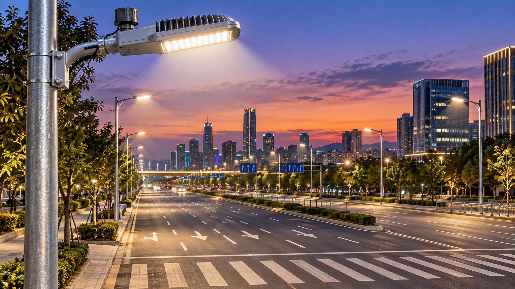
A roadway luminaire should not be selected on wattage, headline lumens, or a generic “IP65 LED street light” description. The specifications that determine whether an installation delivers safe visibility and remains serviceable over its design life are the ones that connect the luminaire to the road geometry, local electrical conditions, maintenance model, and control architecture.
For project delivery, the key question is not whether an LED street luminaire meets an isolated datasheet value. It is whether the proposed combination of luminaire, mounting arrangement, driver, surge protection, controls interface, and pole system can meet the required road-lighting calculation and retain that performance under site conditions.
Photometry must match the roadway, not just the lumen package
Luminous flux is only the starting point. A higher-lumen unit can create poor uniformity, excessive glare, light spill, or wasted energy if its optical distribution does not fit the carriageway width and mounting layout.
The required evidence is a verified photometric file for the exact luminaire configuration: LED package, optic, drive current, tilt angle, and, where relevant, shielding accessory. IES and EULUMDAT files are commonly used in lighting-design software, but a file alone is not enough. Its source and test basis should be clear. Photometric testing to IES LM-79 is a widely recognized method for electrical and photometric measurements of solid-state lighting products.
Roadway calculations should be based on the governing local design rule. Depending on the jurisdiction, this may reference EN 13201, CIE guidance, IES roadway practice, or a national or municipal specification. The applicable requirement may be framed around luminance, illuminance, uniformity, threshold increment or disability glare, surround ratio, and environmental zone limits. These metrics cannot be substituted for one another simply because a design reaches a target average lux value.
- Road width and lane count: determine how far the optical distribution must project laterally.
- Mounting height, outreach, and setback: affect spacing, glare, and the amount of light reaching the far side of the roadway.
- Arrangement: single-sided, staggered, opposite, central median, and high-mast layouts require different distributions.
- Conflict areas: intersections, pedestrian crossings, roundabouts, and merging lanes often need a separate calculation rather than an extension of the main-road layout.
- Road surface assumptions: luminance-based designs depend on the selected pavement reflection class. An incorrect assumption can make a compliant calculation misleading.
It is also important to establish the maintenance factor before approving the calculation. Initial output is not the same as maintained output. Dirt accumulation, lumen depreciation, optical aging, and planned cleaning intervals all affect the maintained result. A supplier should state the assumptions rather than presenting a calculation with an unexplained maintenance factor.
Rated life needs a clear performance definition
“50,000 hours” has limited value unless the survival and light-output criteria behind it are specified. LED packages can retain a high percentage of output while drivers, gaskets, surge devices, connectors, or control nodes become the practical cause of field failures.
For the LED light source, IES LM-80 data and TM-21 projections are commonly used to assess lumen maintenance. They should be interpreted carefully: LM-80 tests the LED package under controlled conditions, while the actual junction temperature and thermal environment inside the finished luminaire determine how applicable that data is. A package-level projection does not by itself prove the life of the complete street luminaire.
A more useful submittal identifies the expected lumen-maintenance point, the driver rated life, the operating ambient temperature range, and the warranty conditions for each major component. It should also state whether failure of an individual LED, a driver, a photocell receptacle, or a surge protection device requires replacement of the whole fitting or can be addressed in the field.
Thermal design is an operational specification
Outdoor lighting must work in summer heat, direct solar exposure, stagnant air, cold starts, and, in some locations, dust or salt-laden atmospheres. Heat is particularly significant because it affects LED output, driver life, capacitor aging, and the reliability of electronic controls.
Project specifications should require an ambient-temperature rating that reflects the actual installation environment, not only a laboratory reference condition. Confirm whether the published wattage and lumen output apply at the site’s high ambient temperature. Where units are mounted in enclosed canopies, tunnels, restricted-airflow structures, or on dark poles exposed to strong sun, the thermal duty may differ substantially from a free-air roadway installation.
Housing material and fin area are relevant, but they do not replace thermal evidence. The meaningful issue is whether the complete luminaire has been designed and tested to operate within component limits at its declared ambient range. Temperature protection behavior also matters: a fitting that automatically reduces output to protect itself may remain functional, but it may no longer meet the designed lighting class.
Ingress, corrosion, and impact ratings must reflect the site
Ingress protection is often treated as a simple pass/fail line item. Under IEC 60529, however, IP ratings describe resistance to ingress of solids and water under specified test conditions; they do not establish resistance to corrosion, ultraviolet degradation, chemical exposure, or sustained pressure washing.
For general exposed roadway use, IP65 is frequently specified because it indicates dust-tight construction and protection against water jets. The required rating should still be read alongside the actual environment. Coastal roads, industrial areas, flood-prone underpasses, and sites subject to aggressive cleaning procedures may require additional sealing, material, coating, connector, and corrosion-resistance review.
IEC 62262 IK ratings provide a separate measure of impact resistance. They can be relevant in vandalism-prone public areas, but the rating should apply to the finished luminaire and its vulnerable components, not only to a housing sample. Lens material is another practical point: its impact resistance, yellowing behavior, and resistance to cleaning chemicals can influence both durability and long-term photometric performance.
For steel poles and brackets, coating system, galvanizing specification, base detail, drainage, fastener material, and dissimilar-metal contact deserve the same scrutiny as the luminaire housing. A durable LED street luminaire cannot compensate for premature corrosion in the support structure.
Surge protection should be designed around the electrical network
Surge damage is a common source of premature outdoor-lighting failures, particularly on long feeder runs, exposed overhead networks, or sites with frequent switching events and lightning activity. A quoted “10 kV surge protection” value is not a complete design basis.
Check the surge protection device configuration, replacement status, indication method, and test standard. IEC 61000-4-5 is commonly referenced for surge-immunity testing, while IEC 61547 addresses electromagnetic immunity requirements for general lighting equipment. The project electrical design should also consider upstream protection, grounding quality, cabinet protection, pole bonding, and the coordination of protective devices. A luminaire-level device cannot solve a poorly designed earthing or distribution system.
Where maintenance access is difficult, a failure indicator or remotely reported surge-protection status can be more valuable than a higher nominal rating with no practical way to identify failure. The project should define the acceptable response when the surge device reaches end of life: continued operation with reduced protection is not equivalent to a fully protected installation.
Controls compatibility must be settled before procurement
Dimming and remote monitoring can reduce energy use and improve fault visibility, but only when the luminaire interface, driver, controller, network, and asset-management platform are compatible. “Smart-ready” is not a technical specification.
The required interface should be written into the submittal requirements: for example, 0–10 V, DALI or DALI-2, or a specified standardized socket and control-node arrangement. In North American projects, ANSI C136.41 receptacles are often used for interoperable lighting-control connections. Zhaga Book 18 is another recognized interface approach for outdoor luminaires and control modules. Neither should be assumed unless it is part of the project architecture.
Controls review should cover more than dimming. Confirm default behavior after communications loss, clock synchronization, photocell operation, local override, cybersecurity responsibilities, data ownership, and commissioning procedures. A system that returns every luminaire to full output after a network interruption can materially alter the predicted energy case. Equally, a node replacement process should not require a proprietary technician or a platform migration for a routine fault.
Electrical and mechanical interfaces affect installation risk
Before a purchase order is released, dimensional and connection details need to be frozen. These include spigot diameter, mounting orientation, allowable tilt, luminaire weight, wind-exposed area, cable-entry direction, terminal capacity, fuse arrangement, access to the driver compartment, and tool requirements for opening the fitting. Small interface mismatches can create field rework across an entire route.
Wind loading should be assessed as a pole-and-luminaire assembly using the local structural code and site wind conditions. A pole’s stated wind resistance is not interchangeable with the luminaire’s projected-area data. The bracket, anchor bolts, foundation, and mounting height must be assessed together.
For installations where trenching and grid extension are disproportionate to the road segment’s value, an off-grid system adds another layer of specification discipline. The lighting duty must be matched to solar resource, battery autonomy, seasonal operating profile, panel orientation, and shading risk. A configuration such as Solar Street Lighting | SL-004 illustrates the type of information that should be reviewed for this application: system power range, LiFePO4 battery life, photovoltaic conversion performance, operating-temperature range, IP rating, pole geometry, and wind resistance. Those values are inputs to a site-specific energy-balance calculation, not a substitute for one.
Submittals should prove configuration control
Roadway projects often fail at the handover stage because approved samples, calculation files, delivered units, and warranty records do not describe the same configuration. The submittal package should link a unique model code to the photometric file, driver, LED current, optic, CCT, control interface, surge device, finish, mounting adapter, and declared ambient rating.
Color temperature should also be set by the project requirement rather than treated as a cosmetic preference. It influences visual appearance, ecological considerations, glare perception, and local approval conditions. If a color tolerance is specified, confirm the measurement basis and whether replacement modules will maintain a consistent appearance over time.
The most defensible selection is therefore not the unit with the strongest individual headline figure. It is the LED street luminaire whose photometry is valid for the road layout, whose protection and thermal design fit the environment, whose electrical and control interfaces fit the infrastructure, and whose documented configuration can be installed, maintained, and verified without ambiguity.
◉ MESSAGE
Blog
- LED Street Luminaire Specifications That Matter for Roadway Projects
- What to Evaluate When Selecting a Smart Street Lamp Manufacturer
- How to Prepare a Compliant Solar Lighting Bid for Public Infrastructure Projects
- LED Street Lighting Solutions for Urban and Municipal Roads
- LED Street Light Installation Guide for Road Projects
- LED Street Light Lifespan: How Long Do LED Road Lights Last?
- LED Street Light IP Rating: What Should Buyers Choose?
Message