
How to assess shading risks in an urban solar lighting project
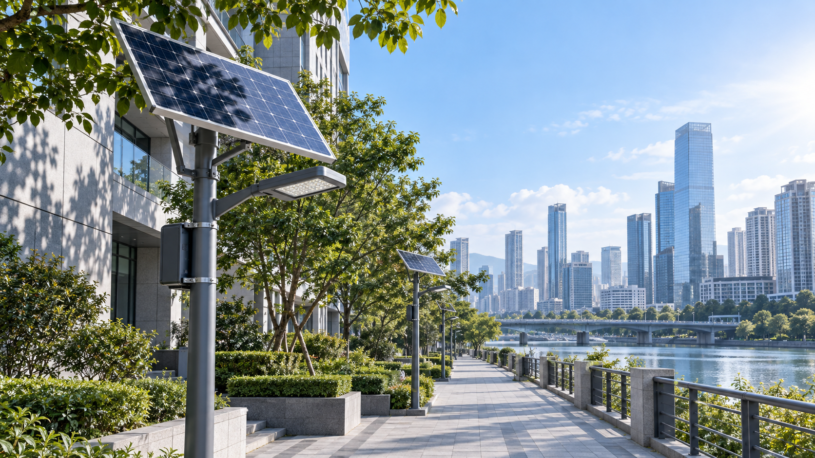
Assess shading risk by comparing the sunlight available at each proposed panel position with the energy needed through the most demanding operating season. A clear view of the sun at midday is insufficient evidence: buildings can remove valuable charging hours, trees change through the year, and winter combines shorter charging periods with longer lighting schedules. In an urban solar lighting project, the assessment should produce a location-specific energy balance and a clear decision about panel placement, equipment sizing, or an alternative power supply.
Establish the lighting demand before judging the site
Start with the intended nightly operating profile. Record luminaire power at each dimming level, the duration of each period, and the consumption of controllers, communications equipment, and sensors. If motion detection raises output, include a realistic allowance for repeated activation. A busy pedestrian route can spend considerably longer at full output than an initial control schedule suggests.
Nightly energy demand equals the sum of power multiplied by operating time across all scheduled periods, plus auxiliary consumption. Keep the calculation boundary consistent: energy measured at the battery must include downstream losses that are absent from a calculation based only on LED power.
Define the required lighting performance and permitted control changes at the same time. Energy savings from dimming are useful only where the resulting illumination remains suitable for the route. Otherwise, an apparently balanced solar design simply transfers the shortfall into reduced nighttime performance.
Map obstructions from the actual panel position
Survey each candidate location at the proposed panel height, orientation, and tilt. Ground-level photographs can misrepresent the view available above a wall or beneath a tree crown. Record the direction, height, and distance of buildings, balconies, parapets, signs, trees, and nearby lighting structures. Include obstructions on the proposed assembly itself, such as brackets or a luminaire positioned above the panel.
A horizon survey or calibrated fisheye image, combined with sun-path software, reveals when each obstruction intersects the sun. Confirm coordinate accuracy and orientation; an incorrect north reference shifts the predicted shadow periods. Surveys near steel structures also require care because magnetic compass readings can be distorted.
For a simple obstruction on level ground, its elevation angle can be estimated from the arctangent of its height above the panel divided by horizontal distance. This supports initial screening, but complex rooflines and tree crowns need a fuller outline. A building blocks direct sunlight only when the sun falls behind both its horizontal extent and its apparent height.
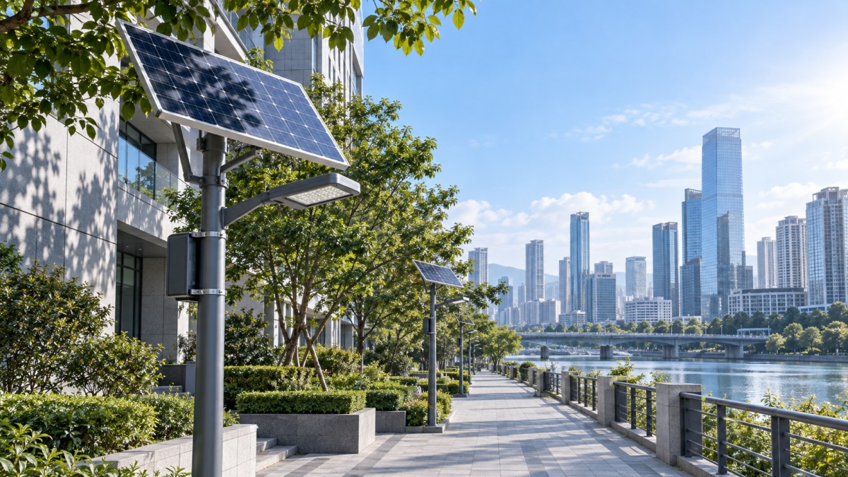
Overlay seasonal sun paths on that obstruction outline. Examine the lowest-sun period and the months when local cloud conditions reduce solar availability. Winter is often restrictive, but a cloudy or rainy season can govern the design elsewhere. Use solar geometry appropriate to the location rather than assuming a south-facing arrangement suits every hemisphere or latitude.
Distinguish lost sunlight from lost electrical output
Shadow duration alone does not quantify the energy penalty. Losing an hour with strong sunlight incident on the panel has a different effect from losing an hour near sunrise. Use hourly solar resource data and the proposed panel geometry to weight each shaded interval. Annual irradiation totals conceal short seasonal deficits that matter to an independently powered light.
Separate direct sunlight from diffuse sky radiation. A panel behind a building can still receive diffuse light, although a narrow street canyon also restricts its view of the sky. Treating every shaded interval as zero generation exaggerates losses; assuming diffuse light compensates for the obstruction understates them.
Partial shading also introduces electrical effects. A narrow shadow across certain cells can reduce output beyond the fraction of panel area covered. The result depends on cell interconnection, bypass diode layout, and controller behavior. Request the actual module layout and relevant shading information before accepting an estimate based solely on shaded surface area. An MPPT controller cannot recover sunlight that never reaches the cells.
Trees need separate treatment from solid structures. Record species where identifiable, canopy density, seasonal leaf cover, and expected growth. Leaf loss improves winter exposure only for deciduous planting, and bare branches still cast shadows. Base the assessment on a realistic future canopy; any reliance on pruning needs an agreed maintenance arrangement.
Test the difficult sequence of days
Calculate energy reaching the battery after shading, module temperature effects, wiring losses, and controller losses. Then simulate battery charging and discharge across consecutive days using the lighting schedule. Include battery temperature limits and the usable capacity expected at the selected design age. Nominal capacity alone overstates the energy available when reserve limits or operating conditions restrict discharge.
A monthly energy balance is useful for screening, but it cannot reveal every failure pattern. Several dull days followed by a heavily shaded recovery day can leave the battery depleted even when the monthly generation total appears adequate. Use time-series weather data where available and document whether it represents typical conditions or a more demanding sequence.
Battery autonomy and recharge capability must be assessed together. More storage delays depletion but does not correct a persistent generation deficit. After a low-charge event, the array needs enough surplus to serve the next lighting cycle and replenish the battery. Evaluate that recovery period explicitly.
Keep unrelated loads outside the solar street-light calculation unless they genuinely share its power supply. For example, a landmark installation using the LED Beam Projector, model GSTYD001, introduces a rated 420W load with a specified 110V–240V AC input. Including such architectural lighting would require a separate assessment of supply conversion and operating hours; its demand cannot be absorbed into a standard solar luminaire allowance.
Choose changes that address the source of the shortfall
Relocation is often the first option worth testing. Moving a panel beyond a roof shadow or tree crown can improve charging without increasing storage. Where the lighting position is fixed by illumination requirements, a separate solar panel location can preserve the intended light distribution. Account for cable length, voltage drop, physical protection, and maintenance access before accepting that arrangement.
Increasing mounting height helps only when the revised geometry clears the obstruction. It also changes wind loading, structural requirements, and access conditions. A modest height increase beside a tall building can add complexity while recovering little sunlight.
A larger panel is useful when sufficient exposure remains to generate the required energy. Confirm that its dimensions, mounting loads, voltage characteristics, and current remain compatible with the structure and charge controller. If the usable charging window is severely restricted, adding panel area may still leave inadequate recovery capacity.
Control changes should follow the lighting requirements established earlier. Scheduled dimming, occupancy response, and low-charge modes each produce different nighttime behavior. Model those behaviors explicitly. Where acceptable lighting cannot be sustained within the available solar resource, assess a remote array, grid supply, or hybrid arrangement before fixing the equipment specification.
Carry the assessment into installation and acceptance
Attach the shading findings to the installation drawings. Record panel coordinates, mounting height, orientation, tilt, obstruction assumptions, operating schedule, and the energy model revision. Identify locations where small installation shifts would move the panel into a shadow. Otherwise, routine adjustments around buried services or street furniture can invalidate an otherwise sound assessment.
Before handover, compare the installed positions with the surveyed geometry and review charging energy, battery state trends, and nighttime operation over representative conditions. A short sunny commissioning period confirms basic function but provides limited evidence of seasonal adequacy. Retain a baseline horizon image and operating data so later charging declines can be investigated against tree growth, new construction, surface dirt, or equipment faults.
◉ MESSAGE

Blog
- How to avoid vendor lock-in in a government smart lighting project
- Sizing the communications power budget for smart city solar street lights
- How energy-saving mode affects solar bollard light operating time
- Comparing lead times from LED street light luminaire suppliers in Europe
- What spare parts support should a smart street light exporter offer?
- Where to place a solar garden light in a partially shaded garden
- Which battery alerts matter in remotely monitored solar street lighting?
Message