
Can solar powered street lighting meet highway uniformity requirements?
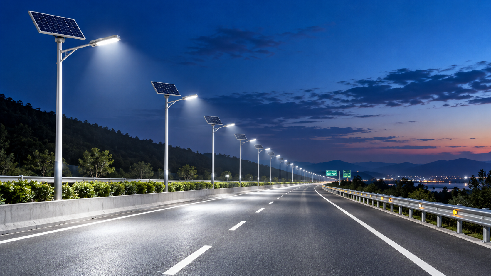
Yes—solar powered street lighting for highways can meet uniformity requirements, but only when the roadway optics, installation geometry, and available energy are designed together. A layout that passes a full-output calculation may become unacceptable if individual lights reduce output differently or batteries cannot sustain the specified lighting level through the night.
During evaluation, the practical concern is often the dark band between poles rather than the brightness directly beneath them. Those bands can make obstacles harder to distinguish despite an acceptable average light level. The decision therefore needs two linked checks: whether the maintained photometric design meets the applicable highway criteria, and whether the solar system can deliver that design under its required operating conditions.
Define the acceptance criteria before comparing luminaires
There is no single uniformity limit that applies to every highway. The governing road authority, roadway classification, traffic conditions, and selected lighting methodology determine the criteria. Confirm the applicable standard and edition in the project specification before accepting any supplier’s statement that a system is “highway compliant.”
Highway assessments commonly use pavement luminance, expressed in cd/m², while some specifications use illuminance, expressed in lux. These approaches are not interchangeable. Luminance calculations account for pavement reflection and prescribed observer positions; an illuminance plot alone cannot establish compliance with a luminance-based requirement.
Check the ratio convention carefully. Minimum-to-average ratios improve as they increase; average-to-minimum ratios improve as they decrease. A ratio without its definition is not sufficient evidence.
Find the cause of dark gaps in the proposed layout
High lumen output does not guarantee useful light between poles. Distribution along the carriageway, coverage across its width, mounting height, outreach, tilt, and pole arrangement determine where the light lands. A broad beam may improve overlap but also increase spill or glare. Increasing tilt to reach a distant lane can create a different compliance problem.
Ask for an isolux or luminance contour plot alongside the numerical results. Repeated low points midway between poles suggest insufficient longitudinal overlap. Dark outer lanes may indicate an unsuitable transverse distribution or mounting position. A high average with isolated bright patches often points to concentrated output rather than balanced coverage.
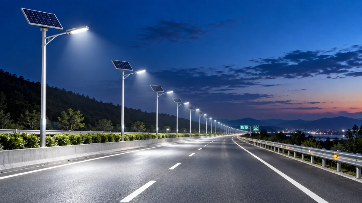
Pole spacing should follow the calculated distribution, not a standard sales layout. Where spacing is constrained by barriers, drainage, access, or existing foundations, evaluate alternative optics and mounting arrangements within those limits. Curves, ramps, merges, and changes in carriageway width need separate attention; a passing straight-road calculation does not validate the entire route.
Solar hardware adds physical constraints. Panels and batteries affect pole loading and servicing arrangements, while roadside obstructions can restrict panel exposure. A photometrically attractive pole position may be unsuitable for energy collection. Resolve that conflict before fixing the layout, rather than reducing nighttime output afterward.
Require a reproducible maintained-lighting calculation
The calculation must use photometric data for the exact proposed luminaire, optical configuration, and output setting. A generic distribution file or a file from another wattage is not enough unless its applicability is technically established.
- Fix the road model. Record lane widths, shoulders, median geometry, mounting coordinates, calculation grids, and observer positions where applicable.
- Declare pavement assumptions. For luminance calculations, specify the reflection characteristics used. Assess additional surface conditions where the project requires them.
- Apply justified maintenance allowances. Account for lumen depreciation and dirt accumulation using the intended environment and cleaning schedule, without duplicating allowances already included elsewhere.
- Calculate every required operating state. Show maintained values, uniformity, glare results, and the locations of minimum values—not just a rendered image.
A design that passes only under initial, clean conditions is not a maintained-compliance design. Likewise, changing the luminaire optic, mounting angle, or driver setting after approval requires checking whether the original calculation remains valid.
Dimming can preserve ratios while still failing the requirement
When all luminaires scale down by the same proportion and retain the same distribution, calculated uniformity ratios generally remain unchanged. However, average and minimum lighting levels decrease. A system can therefore retain an acceptable uniformity ratio while falling below its required maintained luminance or illuminance.
Unequal dimming creates a different risk. Independent battery protection, inconsistent controller settings, or uneven shading can cause adjacent poles to operate at different outputs. The resulting dark gaps may not appear in a calculation that assumes identical output from every light.
Require the proposed control schedule, permitted adaptive-lighting states, synchronization method, and low-battery behavior. Reduced lighting must follow the authority’s permitted operating criteria; it cannot be justified solely by the need to conserve battery energy. Where differential output is foreseeable, assess representative degraded conditions and define how faults will be detected and corrected.
Size energy storage against the required lighting duty
The energy assessment should start with the approved lighting schedule, not with the battery size offered in a catalogue. Calculate nightly consumption from actual electrical demand at each control state, including driver losses and control equipment. Then evaluate whether site-specific solar input can replenish that energy during the design conditions.
Annual average sunshine is an inadequate basis for this decision. The critical period may combine longer nights, lower solar availability, shading, soiling, and reduced battery performance. Use a documented design basis for seasonal generation and the required period of low-sun operation.
- State usable battery energy after temperature effects, discharge limits, and aging allowances.
- Identify shading and panel-soiling assumptions for the installed locations.
- Include conversion losses without counting the same loss twice.
- Show recovery capability after a low-sun period while the lighting duty continues.
Claims such as “several nights of autonomy” are incomplete without the output level, operating duration, battery condition, and recharge assumptions. If the energy balance closes only through unapproved dimming, the proposal has not demonstrated compliance. Larger storage, revised generation capacity, or a grid-backed alternative may be necessary.
Keep product suitability separate from system suitability
A highway scheme may include tunnels or infrastructure areas requiring different lighting equipment. The LED Tunnel & High-Power Floodlight, model SDD-013, is specified for tunnels and critical infrastructure, with a 40–300 W power range, IP66 protection, and several beam options. Its specified input is AC90–305V, so it is not a direct battery-connected solar street-lighting fixture.
Using such an AC-input product within a solar-powered installation would require a separately engineered power-conversion arrangement and its associated losses. Its listed beam angles also do not establish highway uniformity: the selected configuration still needs appropriate photometric data and a project-specific calculation.
Make acceptance evidence part of the selection
Before approval, obtain the calculation files, exact luminaire configuration, maintenance assumptions, energy model, control settings, and fault-response description. Keep the photometric and energy submissions linked: the output assumed in one must match the electrical demand and schedule used in the other.
Commissioning should verify mounting geometry, programmed output, and field measurements under the agreed method. Record battery state and control mode during testing so a passing measurement is not mistaken for proof of sustained operation. Longer-term monitoring should reveal low-energy events and uneven dimming between poles.
Accept the solar option when both the maintained roadway calculation and the seasonal energy assessment support the required operating states. Hold the proposal for revision when compliance depends on ideal battery conditions, undocumented pavement assumptions, or output reductions that the roadway authority has not approved.
◉ MESSAGE

Blog
- How to avoid vendor lock-in in a government smart lighting project
- Sizing the communications power budget for smart city solar street lights
- How energy-saving mode affects solar bollard light operating time
- Comparing lead times from LED street light luminaire suppliers in Europe
- What spare parts support should a smart street light exporter offer?
- Where to place a solar garden light in a partially shaded garden
- Which battery alerts matter in remotely monitored solar street lighting?
Message