
How to verify an intelligent street lighting manufacturer's dimming claims
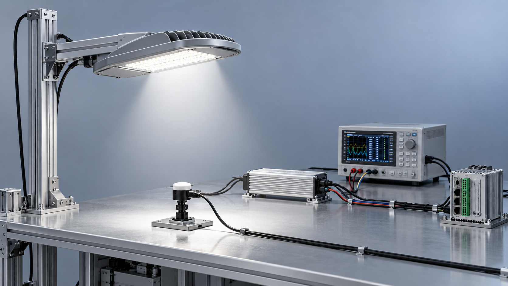
A claimed dimming range tells you little about actual road performance. Verify it through measured light output, input power, flicker, and complete control-system response.
For technical evaluators, an intelligent street lighting manufacturer should provide repeatable evidence for the proposed luminaire, driver, firmware, and controller combination before procurement approval.
The central question is whether dimming remains stable, predictable, and compatible with required road lighting performance across operating conditions, including communication failures and power restoration.
This guide explains which evidence to request, how to reproduce meaningful tests, and how to turn broad supplier promises into measurable project acceptance criteria.
What does the manufacturer actually mean by “1–100% dimming”?
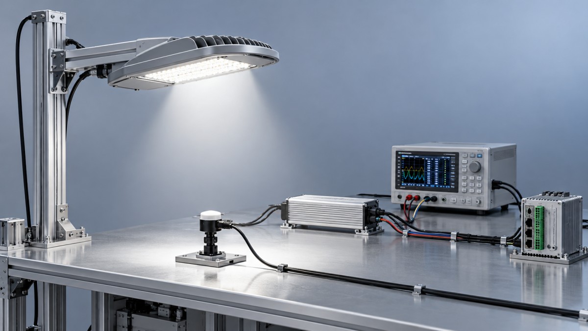
Start by separating the control command from the physical result. A one-percent command does not necessarily produce one percent of the luminaire’s full light output.
Ask whether the stated minimum refers to commanded level, driver output current, measured luminous flux, or electrical input power. These quantities are related but unequal.
Also establish whether the range includes continuous dimming, discrete steps, or dim-to-off operation. A luminaire that switches off below ten percent has a different capability.
Require the supplier to state the dimming curve, minimum stable output, transition behavior, and measurement conditions. Record any restrictions associated with particular drivers or controllers.
A useful claim sounds like “stable measured output down to five percent of stabilized full output under specified conditions,” supported by a documented test method.
Which evidence should you request before arranging a demonstration?
Request reports identifying the exact luminaire model, driver model, controller, firmware versions, supply conditions, ambient temperature, and measurement equipment. Brochure-level family descriptions are insufficient.
Ask for raw readings alongside graphs. At each test point, obtain the command value, measured light output, input watts, power factor, and stabilization time.
Full-output photometric reports establish baseline performance, but they cannot independently prove the entire dimming range. Confirm which reduced-output operating points were actually measured and documented.
Check whether testing covered complete luminaires or only drivers. Driver measurements alone cannot establish luminaire light output, thermal behavior, or compatibility with the proposed controls.
Where independent reports are supplied, verify the laboratory’s relevant accreditation scope and sample identity. An accredited laboratory logo does not establish coverage of every claim.
Freeze the tested configuration in the procurement specification. Any proposed driver substitution or firmware change should trigger an assessment of whether repeat testing is necessary.
How can you measure dimming performance without misleading results?
Use production-representative samples and the proposed control equipment. Agree on sampling across relevant configurations and manufacturing batches, with broader checks where component variation creates risk.
Operate each sample at rated supply conditions and allow thermal stabilization before establishing its full-output reference. Record ambient conditions and the stabilization rule used.
Measure luminous flux with suitable laboratory equipment when verifying percentage-output claims. A fixed illuminance sensor can support comparative checks if geometry and conditions remain controlled.
However, a single illuminance reading cannot establish total luminous flux or road uniformity. Document exactly what each measurement demonstrates before interpreting the resulting percentages.
Test descending and ascending levels, including full output, common scheduled settings, the claimed minimum, and intermediate points near any suspected instability or sudden output change.
Repeat the sequence to expose hysteresis, inconsistent transitions, or drift. Include the project’s specified supply-voltage range and relevant temperature conditions where testing facilities permit.
Calculate relative light output using stabilized measured output at each setting divided by the full-output reference. Calculate relative input power separately using measured watts.
Compare these curves rather than assuming they match. Fixed electronics consumption means reducing light output by half generally does not halve total electrical input power.
For projected savings, apply measured watts to the actual operating schedule. Include controller consumption and relevant network equipment within the stated system boundary for comparison.
What should you check at low output besides visible flicker?
Low-output instability can appear as pulsing, intermittent extinction, delayed startup, or differences between nominally identical units. Observe operation after stabilization and during repeated level changes.
Measure temporal light modulation with suitable equipment and a declared method. Where relevant, report PstLM and SVM, while confirming their applicability to project requirements.
A phone camera can reveal suspicious banding, but camera settings and rolling shutters affect results. Treat footage as diagnostic evidence rather than a compliance measurement.
Request measurements at full output, typical night settings, and the claimed minimum. A full-output flicker result cannot establish performance throughout the entire dimming range.
For areas involving moving vehicles or machinery, assess temporal artifacts against the application’s risks. Agree on metrics and acceptance limits before evaluating the supplier’s results.
Also check color consistency where relevant, audible noise, and reliable restart at low settings. Record whether problems affect individual samples or recur across the configuration.
Will scheduled dimming work through the complete control system?
Bench performance does not establish system performance. Send commands through the proposed management platform, gateway, network, luminaire controller, and driver using the intended project configuration.
Verify the exact control interface and supported functions. DALI, 0–10 V, and wireless systems require different checks; a protocol label alone does not guarantee interoperability.
For analog interfaces, confirm signal polarity, voltage behavior, and dim-to-off support. For digital systems, verify addressing, curve settings, supported commands, and relevant device compatibility.
Test individual commands, group commands, scheduled changes, and overrides. Measure response time and confirm physical light output instead of relying solely on dashboard acknowledgments.
Interrupt communications and restore power deliberately under controlled conditions. Check fallback output, retained schedules, clock synchronization, and recovery behavior against the project’s operating requirements.
Specify whether schedules execute locally or depend on cloud connectivity. That distinction determines what happens during network outages and how recovery should be tested.
Use a representative field pilot to evaluate coverage, command completion, and synchronization across multiple luminaires. A successful single-device demonstration cannot validate an entire deployment.
How should you define pass or fail for procurement?
Build acceptance criteria around the operating schedule and applicable road lighting requirements. A technically stable minimum setting may still provide inadequate visibility for the location.
Check maintained lighting performance at each proposed operating level, including relevant illuminance or luminance, uniformity, and glare requirements. Evaluate adaptive operation under applicable local rules.
Set tolerances before testing and account for measurement uncertainty. The following framework identifies what to specify; numerical limits must reflect the actual project requirements.
Keep mixed outdoor systems within clear test boundaries
Urban projects may combine road lighting with architectural effects or projection. Give each subsystem its own performance criteria while testing any shared scheduling dependencies.
For example, the Laser Engineering Projector JGTYD-011 lists 8,000 ISO lumens and LAN, RS232, and HDBaseT connectivity for large-scale visual installations.
Those specifications do not establish streetlight dimming capability or shared-platform compatibility. Verify projection controls separately, and confirm environmental protection and installation suitability for the location.
Make verified behavior the basis of your supplier decision
Approve an intelligent street lighting manufacturer when documented measurements, repeatable demonstrations, and field results support the proposed configuration against agreed acceptance criteria for your project.
Lishida Smart Lighting’s integrated product, control-system, and project-support scope provides a practical basis for requesting coordinated technical submissions covering equipment selection, system integration, and commissioning.
Require those submissions to identify configuration details, measured performance, and recovery behavior. This gives evaluators a defensible decision and contractors a clear commissioning baseline.
◉ MESSAGE

Blog
- How to avoid vendor lock-in in a government smart lighting project
- Sizing the communications power budget for smart city solar street lights
- How energy-saving mode affects solar bollard light operating time
- Comparing lead times from LED street light luminaire suppliers in Europe
- What spare parts support should a smart street light exporter offer?
- Where to place a solar garden light in a partially shaded garden
- Which battery alerts matter in remotely monitored solar street lighting?
Message