
Architectural LED Lighting: Choosing Beam Angles for Facades
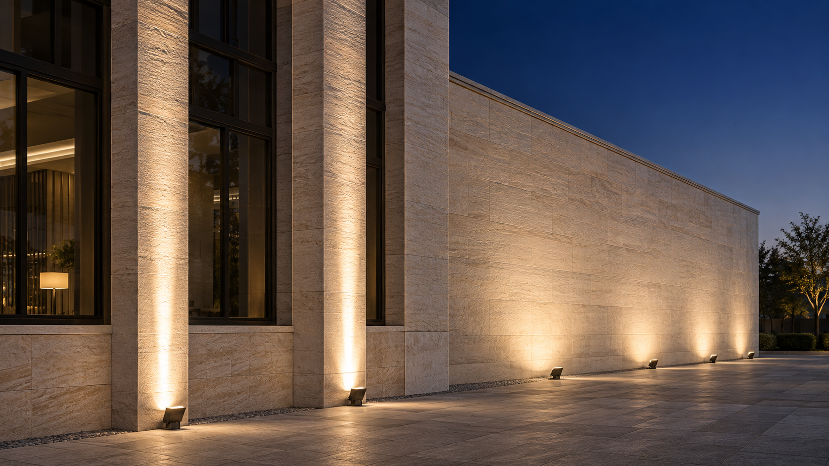
The best beam angle for a facade is the one that puts enough light on the intended architectural surface without creating distracting hot spots, glare, or spill. Narrow beams are useful for tall, slender features and long throws; wider beams suit broader surfaces when the mounting position allows sufficient overlap. Neither is automatically more efficient in a finished design.
For technical evaluators, the choice starts with the facade geometry and the available mounting positions. Beam angle, aiming direction, fixture spacing, and light output must then be assessed together. A distribution that looks appropriate on a product sheet can behave differently once it strikes a wall at an oblique angle or passes across recessed windows and projecting details.
Start With the Surface, Not the Angle
Divide the facade into areas according to what the lighting should reveal. A row of columns may need individual accents, while the wall behind them needs a quieter, more continuous treatment. A textured stone surface may benefit from light arriving close to the wall, whereas a glazed section may produce unwanted reflections under the same arrangement.
For a narrow architectural element, a tight beam can keep light on the feature and limit illumination of adjacent windows. It also demands accurate aiming: a small change in direction can move the brightest part of the beam away from the target. On a broad wall, a wider distribution can reduce the number of visible streaks, but it may also spread light beyond the facade or leave upper areas underlit.
Facade height alone does not determine the answer. A tall elevation viewed from across a plaza may need a broad visual hierarchy, with selected details brighter than the background. The same elevation viewed at close range may expose uneven patches and glare that are less apparent from a distance. Establish the principal viewing positions before judging whether a proposed pattern is acceptable.
Use Beam Spread as a Starting Estimate
For a symmetric beam aimed perpendicular to a flat surface, a first approximation of beam diameter at the target is:
Beam diameter = 2 × distance × tan(beam angle ÷ 2)
At a throw distance of 10 metres, a 10° beam has an estimated diameter of about 1.75 metres, while a 30° beam covers about 5.36 metres. This is a useful way to compare optics early in the design, but it is not a prediction of a uniformly illuminated circle.
Beam angle describes the angular width of a distribution at a specified intensity threshold. It does not indicate that illumination stops at the edge, and it does not describe how evenly light is distributed inside it. Check the photometric definition used in the product data and examine the full distribution, including light outside the stated angle.
Most facade installations also depart from the simple perpendicular example. A ground-mounted fixture aimed up a wall produces an elongated pattern, with different distances and incidence angles across the surface. Projecting cornices, balconies, and window reveals can interrupt that pattern. Use the formula to narrow the options, then model the actual geometry with the luminaire’s photometric file.
Balance Throw, Spacing, and Uniformity
A narrow beam can deliver more intensity toward a distant target when compared with a wider distribution from the same light source, but that concentration comes with tighter coverage. If several narrow beams are used across a wide facade, insufficient overlap can create pronounced bands of light and dark. Increasing fixture spacing may reduce the number of luminaires, but it can also make those bands more conspicuous.
Wider optics can provide more overlap at a given spacing, although they may require more output to maintain the desired illuminance at the far end of the facade. The result depends on the complete intensity distribution, not the nominal beam angle alone. Compare photometric files for the specific output and optic combination rather than assuming that two fixtures with the same stated angle will produce the same appearance.
Mounting distance changes the options. Fixtures close to a wall can produce strong vertical streaks and emphasize texture, which may be desirable for selected architectural details but distracting on a large, uneven surface. Moving fixtures farther away can soften the variation across the wall, provided the site has space and the resulting aiming direction does not create glare or spill. If the setback is fixed by paving, planting, or property boundaries, it should be treated as a design constraint from the outset.
For example, the TGD-031 LED Floodlight is offered with listed beam angles from 3° to 60°. That range makes it possible to assess narrow and wider distributions within one product family, but the selected optic still needs to be checked against the mounting position, required output, and facade dimensions. The product’s IP66 rating is relevant to outdoor exposure; it does not establish that a particular beam will deliver the intended visual result.
Check What Happens Beyond the Facade
Light that misses the target can enter upper-floor windows, illuminate neighbouring property, or become visible against the night sky. A wider beam may increase this risk, particularly when the fixture is aimed steeply upward. A narrow beam can also spill significantly if it is poorly aimed or if the target is smaller than the beam at that distance.
Review the distribution from both ends of the light path. On the facade, identify windows, reflective cladding, signs, and surfaces outside the intended composition. At ground level and from nearby buildings, check whether people can see directly into the luminaire. Aiming adjustments, shielding, alternative mounting positions, or a different optic may resolve the issue, but each can change the coverage that initially appeared acceptable.
Surface reflectance affects the visual assessment too. Light-coloured stone can appear bright with less incident light than a dark material, while polished surfaces can direct reflections toward specific viewpoints. A design based only on calculated illuminance may therefore look unbalanced across materials that receive similar levels of light.
Verify the Choice Before Locking the Layout
A useful comparison begins with a lighting model that includes the actual mounting height, setback, aiming angles, facade features, and photometric data. Evaluate candidate optics at the intended fixture spacing and output, and inspect both the illuminated elevation and the surrounding area. If the luminaire has asymmetric optics, use its supplied photometry rather than applying a symmetric beam-spread estimate.
Where appearance or glare is consequential, a nighttime mock-up can expose issues that are difficult to judge on a drawing. Include enough adjacent fixtures to see their overlap, and view the result from the main public approaches as well as from close to the building. Record the mounting position, optic, aiming angle, and output setting so that the approved arrangement can be reproduced.
Before finalising the selection, resolve the trade-off that matters most for each facade zone: precise emphasis, continuous coverage, limited spill, or ease of installation. Different zones may justify different optics. The strongest specification is one that identifies those intended outcomes and leaves a clear basis for checking the installed result.
◉ MESSAGE

Blog
- Urban Lighting Solutions: Comparing Grid and Solar-Powered Systems
- Lawn Streetlight EPC Contractors: Assessing Installation Capability
- Dusk-to-Dawn Urban LED Lighting: Photocells vs Astronomical Timers
- Waterfront Pedestrian LED Lighting: Addressing Glare and Salt Air
- LED Street Light Manufacturers: Evaluating Warranty and Support
- Connected Smart Poles: How Connectivity Enables Remote Monitoring
- Solar Highway Lighting: Managing Battery Failures on Remote Roads
Message